 |
| Bosco Brown checks out the latest snowfall in the back yard. |
I ordered a 7/8 inch stainless shaft from Tim at Down Jersey Marine, in Greenwich, New Jersey, and picked it up a couple of weeks ago -- between snow storms. Tim, who provided my rebuilt Yanmar 1GM early last year, had the shaft carefully fitted to the coupling, and even dimpled for the set screws. He milled the end of the coupling for a perfectly square fit to the engine.
I decided to use a "newfangled" stuffing-less stuffing box made by PYI, Inc. It only cost a bit more than the conventional ones, and has the advantage of being drip-free and needing virtually no adjustment once in place. It consists of a finely milled graphite ring that bears against a finely milled smooth stainless bearing attached to the shaft. It is lubricated by water that flows past the stern bearing and into the shaft tube.
 |
| PYI Packless shaft seal (PSS) set in place on shaft. |
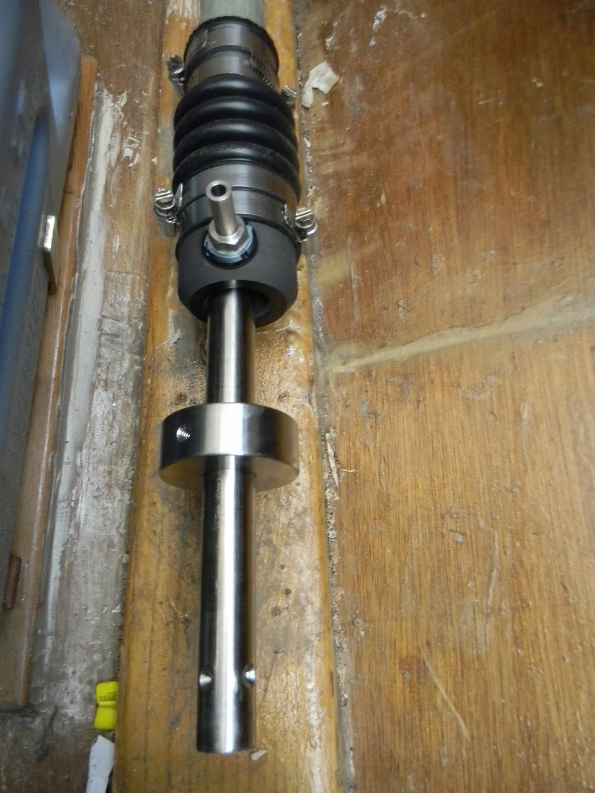 |
| The stainless collar gets tightened on the shaft. Rubber O-rings keep it sealed. |
 |
| PSS fully assembled, shaft and coupling locked in. Waterlock exhaust at bottom of photo. |
Once the engine and shaft were set, I turned my attention to final rudder installation. I had a bit of trouble with the lower pintle and gudgeon, which absolutely did not fit as they were supposed to. When positioned on the deadwood, at the required angle, the gudgeon could not be fastened. It's arms were nearly parallel to the edge of the deadwood. Finally, I reversed the pintle and gudgeon, mounting the pintle upside down onto the deadwood, and the gudgeon upside down onto the rudder. That worked out fine, but I was very disappointed that the extremely expensive "custom" casting for Oughtred's Grey Seal made by Classic Marine in the UK was not what Iain's plan called for at all. If duty and shipping were not so high, I probably would have sent the pieces back. In the end, the setup worked OK, but I could have had an "off the shelf" set that worked just as well for a much, much cheaper price.
 |
| Upside down and reversed pintle and gudgeon in place. |
 |
| Just a bit more rudder trimming, and my prop will spin freely |
 |
| Rudder fully mounted and painted. |
I began a bit of wiring by installing my bronze running lights and wiring up the bilge pumps. A 6 circuit switch panel with fuses is mounted to a mahogany chase attached the forward side of the aft cabin bulkhead on the starboard side. That way, I can hide all the wires from view by running them down and either forward or aft below the cockpit sole or cabin sole, as needed.
 |
| Wiring chase glued to bulkhead |
 |
| Starboard running light |
 |
| Ash framing is in place. Aft cross piece will be screwed in place so engine can be removed. |
A real beauty you build!
ReplyDeleteHow are the sailing characteristics at rougher conditions?
Are you satisfied with her stability? Is there anything you would have done an other way?
I am asking, because perhaps i want to build her too. But i have not heard anything about her sailing...
Do you have more pics of her in the water?
I wish you have a lot of fun with her...