Option 1: Accept the situation, enlarge to hole to the desired width, and mount the engine to the starboard side of center in line with the shaft bore. This would have worked, since I made my engine beds wide, and the engine is a very small proportion of the total displacement, but it would have looked strange and amateurish (Even though I am very much an amateur, I don't need to display that fact any more than is obvious and unavoidable.)
Option 2: Use a boring bar to gradually enlarge the hole in the direction needed, i.e., to port. This solution is limited by the total diameter of the final bore. In this case, I needed to move the center of the bore 7/8 inch to port. The initial bore was 5/8 inch, and the final bore would be no more than 1 1/4 inch. That would not give me enough space to recenter the bore and still end up with a round hole.
Option 3: Plug the hole with a dowel and start over. This solution had some appeal, except that I had no reason to believe that re-boring the hole would necessarily produce a better result. I thought all my measurements and jigs were spot on, but obviously I had gone off somewhere. Perhaps a second try would be worse.
Option 4: John Brady, my first boatbuilding mentor and the current CEO of the Independence Seaport Museum offered what he has referred to as a Rube Goldberg solution to a Rube Goldberg problem.
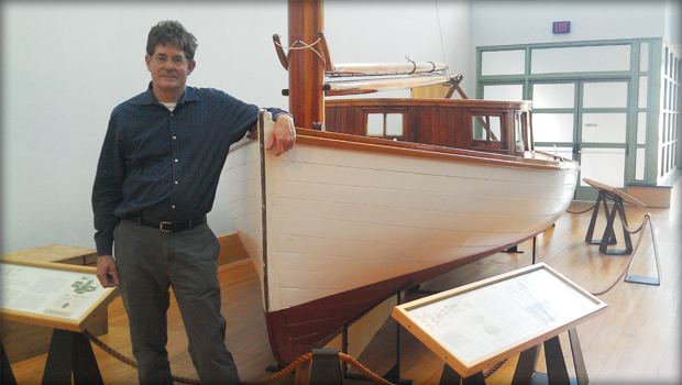 |
| John Brady, ISM CEO and my boatbuilding mentor. Thank you, John. |
He suggested taking a hardwood dowel the same diameter and length as the bore, and cutting a tapered kerf running from the center of the dowel at the deep end to zero at the shallow end.
 |
| John's clever solution to precisely reroute a bore |
I tried it, not really believing it would work, and was amazed that the bore exited the keel exactly next to the edge of the dowel. I made up another identical dowel, followed exactly the same procedure, filling the new bore, and redrilled again. We gained another half dowel width, and were close enough to the center line to make any additional corrections using a boring bar.
In the photo below you can see the centered bore as well as the cut off ends of the two dowels used to straighten the line.
 |
| 1/2 inch boring bar inserted in the realigned pilot |
The boring bar was made of a 1/2 inch diameter 6 foot mild steel rod. I drilled a 3/16 inch hole through the rod to accept a tool steel cutter, and another hole for a set screw to hold the cutter in place. I am waiting for the tool steel bar to arrive so I can make the cutter, so I moved on to other projects.
 |
| The boring bar awaits its cutter. |
 |
| The traveler is set in place. |
 |
| My pile of plumbing stuff |
 |
| Raw water filter assembly mounted on bulkhead, low as possible. |
 |
| Oh no! Not another hole in the bottom! |
 |
| The seacock in positon, but not yet fastened. |
No comments:
Post a Comment